|
|
1st Lower-Surface-Leading-Edge-Tape-Only Performance Measurement (1/29/2011)
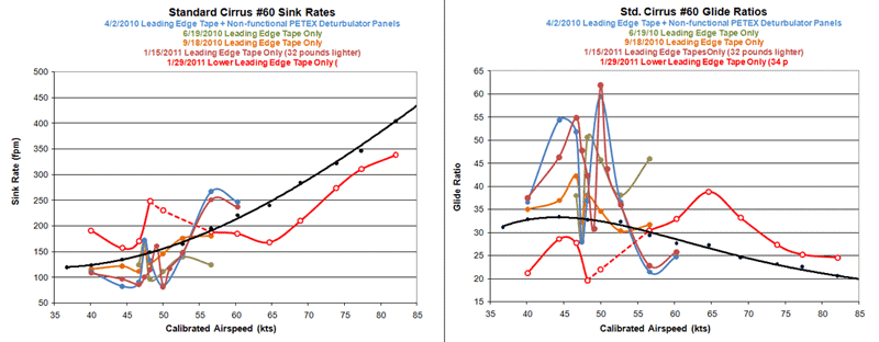
Below are five sets of sink-rate measurements on Standard Cirrus #60 altered only by the (leading edge tape modification). The data on 1/29/2011 (red) were taken with the upper half of the leading edge tapes removed. That is, the wings were clean from a little below the nose upward, but the tape remained in place from that point downward. The dashed part of the curve is where I should have taken closer speed points, but I was sure that the narrow performance notch would not be there so I decided to use the altitude for high speed points instead. So, the dashed part of the curve should be overlooked except for the actual points themselves. I think we can reasonably fill in with our imagination following the pattern of the two sided plots from prior dates show. It is plain to me that I would have found the notch at 51 KIAS again (as on 1/15/2011) if I had only taken that point. Also, for some inexplicable reason, I omitted the 55 KIAS point.
It should be noted that from the inboard end of the ailerons to the tips, a double layer of tape was used to effectively make the tape wider. So, the upper edge of the remaining tape is a double thickness, about .0054 inches thick. I am concerned that this may have tripped the flow at high AOAs.
- The low speed points (40, 45, 48, 50 and 52 KIAS) indicate to me that the notch pattern is still there. At 51 KIAS, where the center of the notch is, the AOA should be about +3.3 degrees and the top edge of the tape is a slight bit below the nose of the wing, so I doubt that the notch comes from top surface early flow detachment as I previously thought. It appears to be a lower surface phenomenon. I think it can be adjusted by an rearward movement of the tape edge to a point where the negative pressure is weaker.
- It is curious that the baseline crossover point for the red curve is at 60 KIAS which is where the AOA is about 0. My wind tunnel simulations (http://www.standardcirrus.org/Airfoil-WindTunnel.php) show -0.2 degrees. I would like to think that the loss came from the double thick tape on the outer panels tripping the flow on the top surface of the wings. That can be fixed easily. But, I noted only the smallest reduction in the straight-ahead stall speed, maybe 0.2 kt from 35 KIAS to 34.8 KIAS. I would think that tripping the flow over the outer wing panels would reduce the stall speed more than that. So, I really don't know the cause of the low speed performance loss. It is only clear that the -/+ performance regions correspond to -/+ AOA regions.
- On the bright side, the high-speed performance boost covers a broad speed range and is pleasantly large. ~39:1 at 70 kt (I incorrectly mentioned 65 kts in my previous message.) is really amazing. I could feel the performance in-flight and it brought a smile to my face. The good news is that the improvement covers a broad speed range. This was not a surprise, as my oil-flow images of the bottom of the wing show good results at 50, 60 and 80 kts. So, I have always suspected that the bottom of the wing was less sensitive to specific speeds as the top. Indeed, the waviness of the high speed points in old deturbulated flights (ala the Johnson tests) is gone.
- Despite the low-speed loss, I am optimistic about this first lower-surface only results. The possibility of developing it into a practical (zig-zag) turbulator tape alternative still seems to be a possibility.
- If the narrow performance notch is a lower-surface phenomenon, then that raises the question of an upper-surface only configuration, or a double surface configuration with the lower-surface notch adjusted out. I believe I could simply go to a narrow, 0.5 or 0.75 inch wide tape and place the operative edge exactly where I want it on both surfaces without being constrained by the tape width. This assumes that the leading edge of the tape will be harmless, or can be smoothed so that it is harmless.
