|
|
|
On this date, I had an opportunity to collect some performance data using a nearly full span application of the parachute fabric membrane over the deturbulator substrates. The deturbulators now run from the wing roots to eight inches short of the outboard ends of the ailerons. The fabric was 3.0 mil ripstop nylon. It was an overcast day with no turbulence above 2500 feet and light winds. For good sink rate measurements, I usually need 6000 to 8000 feet of altitude above the inversion. Today, however, I had only about 2500 feet below a cloud cover. The idea was to get some low speed data points even if the quality might be low. At least I would have some indication whether the porous membrane was working and was able to sustain improved performance for extended periods. Precise measurements are not usually necessary anyway since deturbulator effects are so large. With the altitude available, I was able to measure only the 40, 45, 50, 55, 60, 65 and 70 KIAS points. Below is the result (red) compared to data taken by me in December 2007 (blue) and by Dick Johnson in December 2007 (green). There is enough of a family resemblance in the red curves to indicate that the porous deturbulators did in deed work, but the best performance was not sustained any longer than Johnson was able to hold it in 2006. In fact, the timing is exactly the same.
 It is noteworthy that we now have three similar extreme performance flights, adding yet more evidence that the extraordinary 50 KIAS measurement by Dick Johnson in his third flight on December 13, 2006 was real! Something new in this flight was the large performance improvement at 40 KIAS. I suspect that this is real since it is consistent with the improved stall performance noted in the first surface ventilation flight one month earlier. However, the fabric membrane on this date was much tighter than before. I wish I had taken data just above the stall at 36 KIAS. I expect that it would have been back to baseline since the improved stall characteristics of the first surface ventilation flight were gone and the glider was back to its old habits. As in the prior two similar flights, I calculated a moving average of the performance while holding 50 KIAS. The following image plots the results for all three flights. Until this last flight, I was convinced that this repeating pattern was caused by ventilation latency as the glider descended while cruising. I expected the new surface ventilation configuration to eliminate the latency and allow extreme performance to be sustained indefinitely. But now that view has been discredited.
 The explanation for this repeating pattern appears to lie in the narrow performance speed range and in the aerodynamics of the aircraft. The modified boundary flow resulting from the leading edge tape and deturbulator on the top surface no longer produces the usual transition bubble that holds a fixed position for normal angles of attack. Instead, the flow approaches and departs the narrow deturbulator at grazing angles. This can be seen in oil flow visualizations. The modified flow skips on the surface over, around or near the deturbulator. The region of contact is not stable, but changes greatly with slight changes in AOA. As the glider approaches 50 KIAS, the skip zone centers over the deturbulator and the lift force increases. This and, presumably, a corresponding reduction in drag combine to produce a dramatic performance improvement. However, because the weight and lift are no longer in balance, the glider accelerats slowly upward and slows down accordingly to maintain continuity in the declining total energy. But the test pilot is trying to hold a constant airspeed in order to get good sink rate data. Thus, he instinctively edges the stick forward to maintain 50 KIAS. The reduced AOA then causes the skip zone to slide aft of the deturbulator and performance falls off. The 12/1/07 flight (green curves above) took half the time to run through the scenario. This is likely because I over corrected the airspeed and lost the optimal flow pattern prematurely. If this postulation is correct, it should be possible to extend the period of extreme performance by holding the AOA steady and allowing the airspeed to bleed off until the lift matches the weight again. But the piloting skills needed may be too great. To make this easier, I plan to increase the width of the deturbulator. I expect this to widen the speed range for extreme performance. Modern airfoils with a lot of camber at the rear of the wing may not require such wide deturbulators. The following table lists the three similar extreme performance flights to date (5/22/2009) and contrasts the membrane materials used.
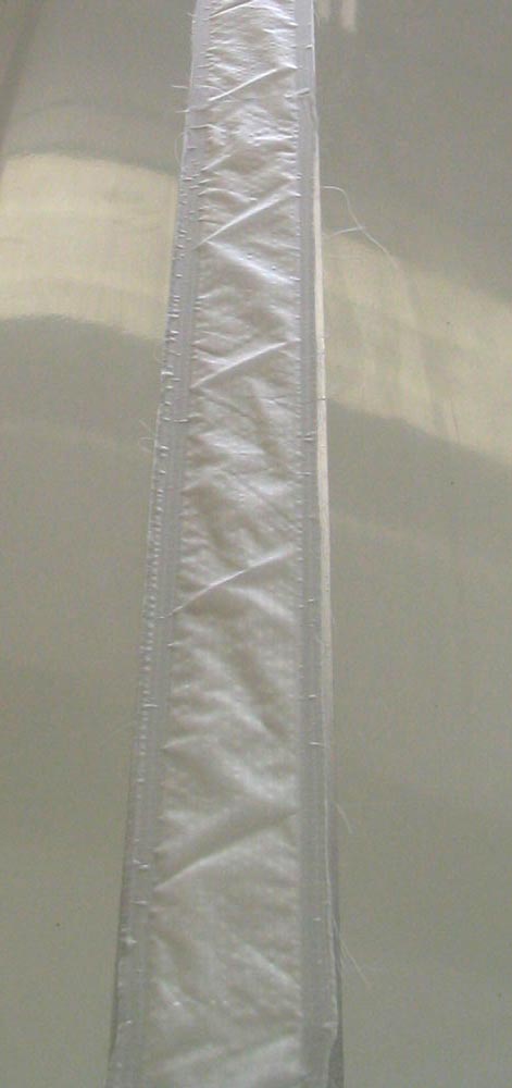
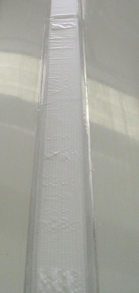
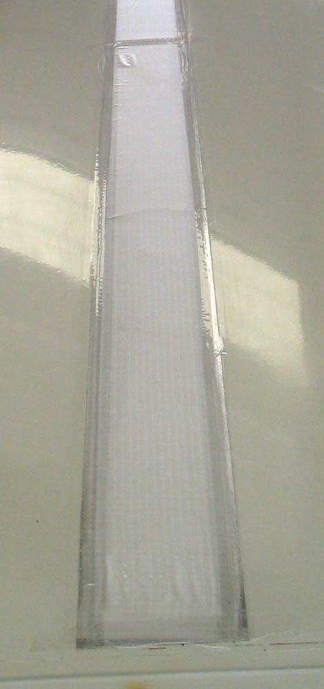
This last flight with porous membranes verified that they work and it seems obvious that the humidity issue that has plagued our project for years is now solved. However, parachute fabric will not be the membrane of choice. The flight on this date, and flights on the subsequent two days, revealed a major problem with expansion and contraction of the fabric with changes in humidity and/or temperature. To see this, look at the three images below. The first one shows a panel that is extremely loose. This is the way I found it upon opening the hangar in the morning. The relative humidity was 50% and the temperature was cool. Thinking that this was too loose, I retensioned the panels as shown in the second image. Then after flying twice, to take the data plotted above and for an hour of thermalling, the membrane had tightened even more.
This large variation in tension with normal changes in temperature and humidity must have a significant effect on the consistency of the performance. Currently, I am searching for better material to use. However, for the time being, I will loosen the fabric membrane sufficiently that it will not become taught under normal flying conditions. This may improve low speed performance down to stall, but it may hurt high speed performance. We'll see. A second modification will be to widen the deturbulator panels by three times. Given the Wortmann airfoils in my wing, I expect this to broaden the performance speed peaks and make holding a high performance speed easier. The clean wing has a transition bubble the holds its position just behind the thickest chord position at normal angles of attack. But the modified configuration changes this so that the flow approaches the surface at a grazing angle at a point that scoots back and forth with the slightest change in angle of attack.
Jim Hendrix |
| © Copyright 2003-2012 Jim Hendrix | Disclaimer |