|
|
2nd, 3rd and 4th Lower-Surface-Leading-Edge-Tape-Only Performance Measurements (9/29/2012)
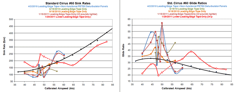
Fig. 1 shows four measurements of performance with a full width application of tape around the leading edge of the wings on Standard Cirrus #60 and one with the tape above the leading edge removed, leaving just the tape below, as before. See Effect of Leading Edge Tapes for details about the installation. Removing the upper part of the tape was done to see the part of the performance change contributed by the bottom surface apart from the upper surface effect. The change was incredibly large with all slow speeds suffering a severe loss and all high speeds a nice improvement. The dividing point, at 60 kts, is the speed that an airfoil simulation indicates as the zero AOA speed. See Wing Airfoil Wind Tunnel Simulations for details. It appeared that all AOAs at which the relative wind saw the forward edge of the tape as a step down suffered a large performance loss; whereas, all AOAs that saw it as a step up ignored the forward edge of the tape, leaving a performance improvement caused by the rear edge of the tape.
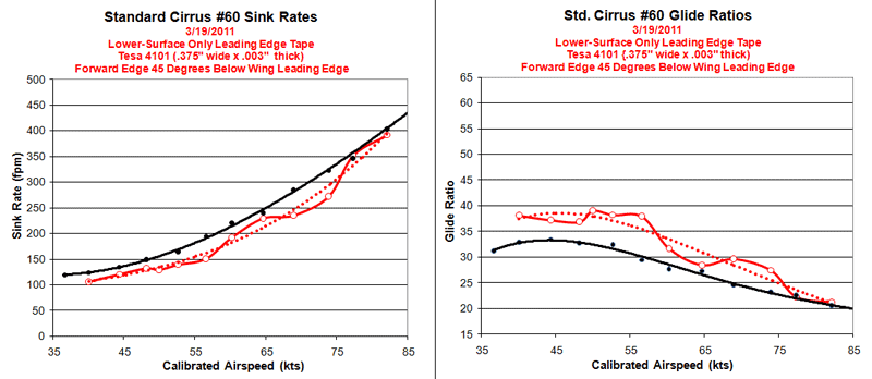
The next step, obviously, was to move the forward edge of the tape down far enough below the leading edge so that it would aloways be seen as a step up. For this, 45º was chosen. A tape that was 1/2 inch wide was chosen, as that would place the rear edge more or less where it was originally, for the inboard wong panel (out to the aileron). From the inboard end of the aileron to the tip, the lower rear edge of the original tape angled aft more than the new tape. I thought the new, more forward location would improve performance, but the data may suggest otherwise. Fig. 2 shows the result from fromving the original tape and replacing it with a 1/2 inch wide tape located 45º under the wing leading edge. The difference is startling, and immediately looks like a practical and easy mod for 15 percent better performance for gliders with Wortmann wings.
But one set of measurements is only perhaps a suggestion, and more are needed, perhaps as many as six to get a really solid reading. It has taken a while, but on Saturday, 9/29/2012, I took two additional sets of measurements over the speed range of 40 to 55 KIAS. The reason that the speed range was so narrow was that I wanted to see if the lower surface tape effect produced a performance notch, like the one that consistently appears right in the middle of the extreme performance peak produced by the upper surface effect (Fig. 1). Also, I had a boundary probe on the upper surface near the leading edge looking for changes in the boundary flow that might correspond to the large performance peaks. For these reasons I took readings in 1 kt increments from 48 to 52 KIAS. As I only had about 3000 feet of clear air above the inversion to work with, I had to omit the high speed points. This decision was somewhat ameliorated by having the high speed measurement from the nose down tape run (red in Fig. 1). Fig. 3 shows the two sets of measurements from 9/29/2012 and one set from 3/19/2011. The red curve is the average. Only two measurements are averaged for the 48, 49, 51 and 52 KIAS points. Three are averaged for the other points.
Although only two measurements each were taken for the 48 and 49 KIAS speeds, they closely agree and strongly suggest that, indeed, the lower surface tape mod produces a performance notch as the upper surface effect does. Fortunately, the lower surface notch appears to only return to baseline performance, without detracting further. While the 45 to 50 KIAS speeds should be avoided, the pilot can know that at least the glider is performing at those speeds as before the mod was installed.
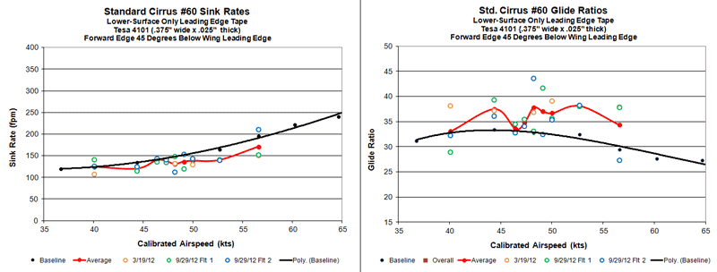
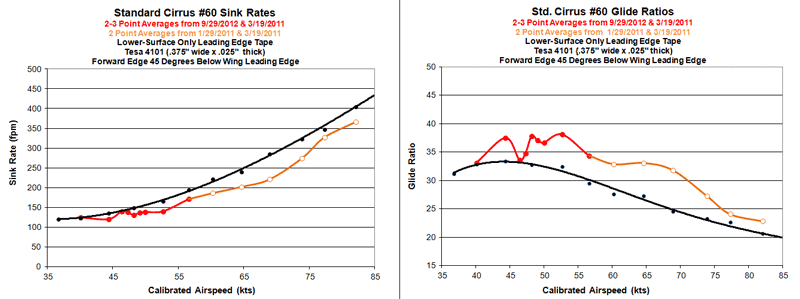
Fig. 4 combines all of the data to date taken on Stancard Cirrus #60 for performance changes due to a lower surface reara-facing step near the leading edge. The afore mentioned measurements from the red curve in Fig. 1 above 60 KIAS are included to give two measurement averages for the high speeds. True, the rear edge of the tape over the outer wing panel is not the same for these two sets of measurements, but at least they constitute an indication of what might be achieved by a judicious angling of the narrow tape to match the original tape's rear edge position.
Independent measurements by Kiley and Shipp appear to show a notch resembling the one in Figs. 3 and 4. With the lower surface tape, and after removing wax from the forward wing lower surface, they obtained the results shown in Fig. 5.
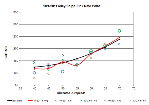
The notch from the top surface effect is very sensitive to airspeed. In Fig. 1, three measurements show the notch precisely at 49 KIAS. However, with a 15% reduction in all up weight, the notch moved up two knots to 51 KIAS. If the Kiley/Shipp data also show a notch, then the difference in speed is probably due to the fact that their data are plotted vs. indicated speed, whereas mine are plotted vs. calibrated speed, which is slower than ASI indicated speeds. Also, there are differences in wing loading and somewhat in the position of the tapes.