|
|
Deturbulated Detached Flow at 50 Knots Indicated Airspeed
|
(click to enlarge images)
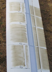
| Before Flight - Overview |

|

|
Top of Outboard Left Wing
Sections 1-4
|
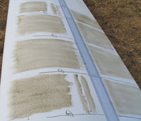
Top of Inboard Right Wing
Sections 5-8
|
| After Flight - Overview |

|

|

|

|
Top of Outboard Left Wing
Sections 1-4
|
Top of Inboard Right Wing
Sections 5-8
|
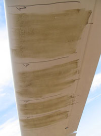
Bottom of Outboard Left Wing
Sections 1-4
|
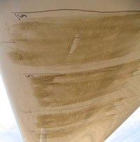
Bottom of Inboard Right Wing
Sections 5-8
|
| After Flight - Top Side - Section 1 |

|
|
Intermediate tape with Tesafilm leading edge smoothing tape.
Deturbulator with unsmoothed leading edge.
Puddled oil pattern in normal detached flow region indicates
higher than normal detached flow starting a few inches after leading edge of wing. Streaming of oil at front of
detached flow area ends after one inch, indicating where the flow is too high to pull the oil along with it.
Smooth oil pattern over and ahead of intermediate tape indicates wider than normal reverse circulation bubble.
Aileron gaps are sealed inside and on bottom side.
Flow starts lifting from surface behind deturbulator, then strikes the aileron gap where it dips and encounters
the leading edge of the aileron. Oil streaming ends within an inch of the aileron leading edge and flows detached
thereafter. Smooth region at rear edge of aileron indicates a reverse flow separation bubble where the separation
is excessive.
|
| After Flight - Top Side - Section 2 |

|
|
No intermediate tape.
Deturbulator with unsmoothed leading edge.
With the intermediate tape removed, the entire flow pattern is changed compared to section 1 above.
The absence of thick runs of oil that end a few inches behind the leading edge, indicates flow closer to the surface,
detaching later and more gradually. The same is true behind the deturbulator where oil runs resembling weak attached
turbulent flow go all the way to the aileron gap. Detachment on the aileron too is more gradual.
Perhaps the square leading edge of the deturbulator is tripping the flow slightly.
|
| After Flight - Top Side - Section 3 |

|
|
No intermediate tape.
Deturbulator with Tesafilm leading edge smoothing tape.
The addition of thin Tesafilm tape to the leading edge of the deturbulator, reduces the tendency to trip the
flow, increasing the level of turbulence over the deturbulator. Again, rapid detachment behind the wing leading edge
is indicated by short thick runs of oil that simply stop flowing.
In this case, however, the smooth reverse circulation bubble is greatly extended forward so that it now covers
most of the detached flow area and merges softly with the onrushing detached laminar flow. One gets the impression that
the height of the conventional transition bubble is greatly reduced along with its penalty in form drag.
Again, as in section 1, separation behind the deturbulator is more agressive as seen by oil runs that simply stop
in their tracks. The trailing edge bubble indication is much wider here than in sections 1 and 2, indicating excessive
detachment about half way across the aileron.
|
| After Flight - Top Side - Section 4 |

|
|
Intermediate tape with Tesafilm leading edge smoothing tape.
Deturbulator with Tesafilm leading edge smoothing tape.
Ditto the comments for section 3, and more so.
|
| After Flight - Top Side - Section 5 |

|
|
Intermediate tape with Tesafilm leading edge smoothing tape.
Deturbulator with unsmoothed leading edge.
Sections 5-8 are located midway between the wing root and the air brake where the airfoil is thicker as a percentage of
the chord, the camber extends to the trailing edge instead of flattening out and there is a reflex on the bottom side
near the trailing edge.
Flow pattern resembles section 1 which has the same tape configuration.
|
| After Flight - Top Side - Section 6 |

|
|
No intermediate tape.
Deturbulator with unsmoothed leading edge.
Leading edge detachment is early and sharp, but oil streaming at the rear of the detached laminar area indicates that
the flow returns to the surface gradually where there would normally be a circulation bubble. This raises concern that
the flow could be tripped by the square leading edge of the deturbulator that ideally should be absolutely smooth.
Again, there is quick detachment behind the deturbulator. Most of the aft wing area shows the oil in its original
condition before the flight, suggesting wide flow separation which is not good.
|
| After Flight - Top Side - Section 7 |

|
|
No intermediate tape.
Deturbulator with Tesafilm leading edge smoothing tape.
Removal of the intermediate tape produces a desirable deturbulated flow pattern over the forward wing area,
with detachment immediately after the leading edge, puddled oil blotches over most of the foreward wing
area, and a broad (flattened?) circulation bubble.
Separation behind the deturbulator is complete with in two inches (oil streams stop flowing) and oil puddles
thereafter suggest detached flow near the surface. This may be the best possible flow pattern.
|
| After Flight - Top Side - Section 8 |

|
|
Intermediate tape with Tesafilm leading edge smoothing tape.
Deturbulator with Tesafilm leading edge smoothing tape.
This pattern is complicated by the intermediate tape and smoothing tapes, but overall resembles section 7.
|
Based on these oil flow indications, we decided to remove the intermediate tape that was needed for the deturbulators
that Dick Johnson tested in 2006.
We also smoothed the leading edge of the deturbulator with shiny, thin Scotch tape.
The very next flight (December 1, 2007)
essentially replicated the third Johnson flight which produced extreme performance.
Jim Hendrix
Oxford Aero Equipment
|


